motor controller for R/C models
microprocessor-controlled
Design by A. Voggeneder and A. Nader
|
| Technical specification
|
| Supply voltage:
|
6 to 10 V
|
| Supply current:
|
<5 mA
|
| Max. output current:
|
40 A
|
| Processor:
|
PIC16C84
|
| Connection:
|
3-pin plug
|
| Application:
|
model boat, car, plane
|
| Versions:
|
unidirectional or bidirectional
|
| Motor brake:
|
internal with unidirectional version
|
| Thermal protection:
|
at 120°C
|
|
Radio-controlled (R/C) modelling seems to fascinate many electronics enthusiasts.
This technical hobby is a melting pot of many interesting disciplines, including
mechanic engineering and electronics. Many 'modellers', and especially newcomers,
start from largely pre-assembled models or kits which allow them to build a model
boat, car or airplane without too much of a risk. All battery-powered models have one
aspect in common: the speed control is based on a variable resistor which is
operated by a servo motor. Anyone who has used such a model for some time will
discover that the variable resistor may run pretty hot, which means that a lot of
energy is wasted in the speed control. A shame, really, because the storage and
retention of sufficient energy to power just about any vehicle is still one of the biggest
problems in model building. Fortunately, there exists a much more efficient
alternative. The present circuit demonstrates an intelligent and low-loss motor
controller which may be built from relatively few parts. The result: one battery charge
will allow the model to drive, fly or sail longer. Because the circuit is relatively easy to
construct, improved efficiency does not come at high cost in this case. Moreover, the
size and weight of the circuit are modest, which is an important aspect in this
context.
A SEAMLESS TRANSITION
As a matter of course, the electronic motor controller was designed to comply with
standards which are widely used in radio-controlled model building. After all, keeping
to the conventions is the only way of making sure that the existing regulator may be
replaced by its modern electronic counterpart. The mechanical speed regulators
which are normally fitted in ready-made models are controlled by a servo motor. The
servo, in turn, is controlled by pulse-width modulated signals supplied by the radio
receiver installed in the model. The pulses that form the servo control signal have a
width between 1ms and 2ms. In this system, a width of 1ms corresponds to
'maximum', 1.5ms, to 'mid-travel', and 2ms, to 'minimum'. These pulses are sent
every 40ms (i.e., at a rate of 25Hz). The servo used has an important function
because it translates the received pulse width into a corresponding movement of a
lever, which changes the setting of the variable resistor via small rod. As a result, the
motor voltage increases or decreases, causing the model to accelerate or slow
down. The all-electronic version described here replaces the servo, the lever, the rod
and the variable resistor in one go. Apart from eliminating the energy waste inherent
to a traditional regulator system, the circuit also saves space and weight in the
model.
The motor control may be built in two versions. For model planes, the control is used
in unidirectional mode (i.e., as an ordinary min./max. regulator). The entire control
range is then used to adjust the speed of the propulsion motor over a large range.
The second version operates as a bi-directional control. This type will be used mainly
in model boats and cars. The span of the control is then divided into two ranges:
'forward' and 'reverse'. The centre position of the control then corresponds to 'off',
i.e., the motor does not run. Because this 'zero' point is rather critical, a certain
'dead' span has been created around it. This is done to prevent the motor reversal
relay from 'chattering'. Because this relay is normally fitted in the vehicle, it is not
found back in the circuit described here.
A motor braking function has been implemented in unidirectional mode. At the zero
setting, this brake short-circuits the motor, allowing the reverse emf (electromotive
force) generated by the motor to rapidly reduce the speed of the model to nought.
To make sure that the interface and the used transmitter work happily together, the
minimum and maximum propulsion power may be programmed, in addition to the
previously mentioned dead zone. In this way, the microprocessor's power is fully
exploited.
THE APPROACH
The complete circuit diagram of the motor control is shown in Figure 1. The
schematic includes all components for unidirectional as well as bidirectional use. The
desired version is chosen before building the circuit. Your choice therefore
determines the components used. The circuit has been kept as compact as
possible. The result: a motor control weighing less than 25grammes.
Figure 1. Circuit diagram of the R/C
model motor controller. The heart of the circuit
is a RISC microprocessor from Microchip Technology Inc.
The (intelligent) heart of the circuit is formed by a PIC microprocessor (type
PIC16C84-04) from Microchip Technology Inc. This miniature RISC processor
contains all elements needed for the project. Because control signals always consist
of logic levels (pulse width modulated logic signals are found at the input as well as
the output), the speed control does not require an A/D converter.
The connection to the receiver is made via a
three-wire link, which is standard in
model building. In addition to the control signal (A), the interface also receives its
supply voltage (+5 volt and ground). In other words, the receiver gets its supply
voltage via the motor control.
The control signal supplied by the receiver is applied directly to pin RB0 of the
microcontroller (IC1). The other inputs of the microcontroller (RB1-RB5) are
connected to pinheader K1, for use during the configuration of the circuit.
Three outputs are significant in the
process of controlling the motor speed. The
signal used to switch the direction relay (bidirectional version) or the motor brake
(unidirectional version) is available at output RA1. Opto-isolator IC3, a type PC827,
is driven via outputs RB6 and RB7. The opto-isolator, in turn, drives the transistors
that determine the current through the motor. Because high currents are not
uncommon in model building, three MOSFETs type BUZ11 are connected in parallel
here, the triplet allowing currents of up to 40A to be handled without problems.
As already mentioned, you have to decide on the function of the circuit before you
start building it. In the bidirectional version, components T5 and R9 are omitted. In
the unidirectional version, D1 and T1 are not required.
The motor is connected between the two terminals marked + and M-. In the
unidirectional version, a diode type MBR2045 (D2) is found across these terminals.
This dual Schottky diode has been specifically developed for heavy-duty
applications, each diode being able to cope with a current of 20A. In this circuit, the
MBR2045 acts as a flyback diode to suppress voltage surges generated when the
motor is being switched. Diode D1 is the flyback diode which is connected across
the relay.
The battery voltage is transformed into a stable voltage of 5V by an integrated
regulator. The 5-V rail is used to power the motor control as well as the receiver.
An NTC (negative temperature coefficient) resistor, R7, allows the motor and battery
temperature to be monitored. The value of the NTC resistor is calculated by charging
capacitor C4 alternately via R6 and R7. Because the value of R6 is known, the
resulting time differences allow the value of R7 to be calculated. At the selected
switching thresholds (defined in the software), the protection is actuated at 120°C
and switched off again at 80°C. If the protection is not required, the NTC may
simply be omitted. The resistance is then, in principle, infinite, which, as far as the
controller is concerned, corresponds to a cold motor or battery.
CONSTRUCTION
Now you know the theoretical details of the circuit, you are ready to start building the
actual thing. The track layout and component mounting plan of the printed circuit
board used to build the control are shown in Figure 2. As already mentioned,
compactness was a prime issue during the development of the circuit. The PCB is
double-sided, and has components at both sides. Where possible, SMDs (surface-
mounted devices) have been applied.
Figure 2. The double-sided board guarantees a compact construction. Components
are fitted at both sides!
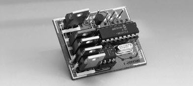
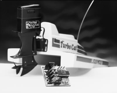
Figure 3. The finished prototype demonstrates the meaning of 'compact'. Thanks to
the use of PIC processor, the unit weighs only 23grammes.
Before you start soldering, you have to select between unidirectional and
bidirectional mode, because that determines the component content of the circuit.
For unidirectional mode, D1 and D2 are omitted, while T5 and R9 are mounted.
opposite applies if the circuit is used in bidirectional mode.
Start by fitting all SMDs at the copper side of the board. This should not be too
difficult or time-consuming if you use a fine-tipped soldering iron. Next, you turn the
board around, and carefully fit the parts at the top side. If you want, you may fit IC1
and IC3 in sockets. A 10-pin header is used for K1. Heatsinks are not required
although pretty large currents may flow in the output stage. None the less, if high
currents are a reality, it is recommended to strengthen the copper tracks through
which the current flows. In practice, that is easily achieved by soldering a short
of thick, solid copper wire onto the relevant track section.
The connections for the supply voltage, the motor, the NTC and the relay are made
via solder pins. After inserting the programmed microcontroller into its socket, the
circuit is ready for use. Because noise generated by, for example, the motor may
upset the operation of the control, it is recommended to fit three 100-nF (0.1-µF)
suppressor capacitors across the motor. One capacitor is connected between the
two motor terminals, and the other two, between the motor terminals and the motor
housing (ground). Finally, we recommend winding the wires that carry the drive
signals from the receiver to the control through a ferrite bead (two or three times),
as close as possible to the receiver.

Figure 4. The circuit may be used to replace the mechanical speed control in
virtually any model, be it a boat, car or plane.
| JP1 |
Maximum forward speed. |
 |
| JP2 |
Maximum reverse speed. |
 |
| JP3 |
Minimum forward speed |
 |
| JP4 |
Reset (When closed during powerup) |
|
| JP5 |
Mode. 1 = Unidirectional, 0 = Bidirectional. |
|
MISCELLANEOUS MATTERS
The mode of the circuit is selected with the aid if jumper JP5.
Fitting it selects unidirectional mode, omitting it, bidirectional mode.
In unidirectional mode, set the joystick on the transmitter to minimum speed, and
temporarily close jumper JP2 (approx. 1second).
This enables the PIC processor to couple the received pulse time to minimum motor speed.
Next, set the joystick to maximum, and briefly close jumper JP1.
This links maximum motor speed to the received pulse time.
The microcontroller then automatically ensures that the entire speed range is coupled to the span of the control signal.
Roughly the same procedure is followed for the adjustment of the bidirectional mode,
only jumper JP2 is then used to determine the maximum reverse speed. Also, the
dead zone may be programmed as an extra. Set the joystick to the position which
you still want to be interpreted as 'zero', i.e., the highest joystick position that causes
zero motor activity later. Briefly close jumper JP3. The controller will record this
setting and store it into its memory. All settings are stored in an EEPROM, which
allows them to be retained for a long time. A reset during which the default settings
are loaded is accomplished by closing jumper JP4 and then switching the supply on.
The controller then loads its (internally defined) pre-programmed values (defaults),
and all user-programmed values are overwritten.
The speed control may then be fitted into the model and connected to the motor, the
receiver and the battery. If you want to make use of the NTC, the component may be
fitted on to the motor or the battery. You may then look forward to many happy hours
racing your model car, sailing your boat or flying your plane.
(960095-1)
COMPONENTS LIST
Resistors:
R1 = 4kOhm, SMD
R2 = 100Ohm, SMD
R3 = 470Ohm, SMD
R4,R6 = 100kOhm, SMD
R5 = 10Ohm SMD
R7 = NTC, 100kOhm
R8 = 1kOhm, SMD
R9 = 10kOhm, SMD
Capacitors:
C1,C2 = 15pF, SMD
C3,C5 = 100nF, SMD
C4 = 10nF, SMD
C6 = 47µF 10V SMD
Semiconductors:
D1 = LL4148*
D2 = MBR2045CT*
T1 = BC517
T2,T3,T4 = BUZ11
T5 = IRF9530
IC1 = PIC16C84 (order code 966510-1)
IC2 = L4940V5
IC3 = PC827
Miscellaneous:
K1 = 10-way pinheader
X1 = 4MHz quartz crystal
Printed circuit board and programmed PIC (IC1): set order code 960095-C
PIC also available separately: order code 966510-1
Printlayout:
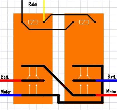
How to connect the relay(s) in bidirectional mode:
The PIC program : Fahrt.asm + Picreg.equ = Fahrt.hex
Mini PIC programmer
Design by Patrick Gueulle
Even with street prices dropping steadily, good PIC programmers remain relatively
costly tools.
Provided you exploit the 'serial programming' mode available on recently launched
PICs (and, in particular, the 16C84), it is feasible to build a surprisingly simple
programmer which is still fully compatible with much of the powerful software now
circulating on the Internet.
SERIAL-MODE PROGRAMMING
Programmable components are increasingly intended to be programmed 'in-circuit'.
The process is also called code downloading, meaning that the relevant chip is
simply connected to a bus consisting of four or five wires.
In this respect, the 'isp' chips from Lattice are the best know examples, although
there are new arrivals all the time. Relative newcomers in the field include certain
MACH types from AMD, whose appearance on the market has not gone unnoticed.
As you are probably aware, several members of the PIC family offer a similar ability
which enables them to be programmed or re-reprogrammed while they remain on
the application board, and you do not even have to remove the supply voltage.
These PIC chips are switched to programming mode by pulling their reset pin
(/MCLR, pin 4) to a high voltage, usually between 12 and 14volts.
From then on, RB6 (pin 12) acts as a CLOCK input, while RB7 (pin 13) is turned
into a DATA input/output line.
The power supply pins of the PIC, Vdd (pin 14) and Vss (pin 5) retain their normal
function, that is, they keep the PIC supply voltage at the nominal value of 5V,
although all other pins are effectively disabled.
In this mode, you may program, read and even clear (erase) the PIC simply by
communicating with it using a serial format on the DATA line. In fact, this closely
resembles the way serial EEPROMs work, as well as some chip cards.
The communication protocol used for serial programming is disclosed in a document
of some 10 pages called PIC16C84 EEPROM memory Programming Specification
which is available from Microchip Technology, or, in electronic form, on the CD-ROM
published by this manufacturer.
Provided you do accept that the present design can not be labelled as a 'production
programmer' the strict rules for programming laid down by Microchip may be relaxed
considerably. So, let's agree on calling the present design a 'prototype' or
'development' programmer.
FREE PROGRAMMING SOFTWARE
Fortuitously, among the less inspiring things found on the Internet, there's also
webbed software for programming PICs. What's more, it's free!
One of these free programs is PIP02. Although still in an early version (1.14), the
program is still very satisfactory. Here it is available as a zip file.
Developed by Antti Lukats of Silicon Studio Ltd., PIP02 assumes that the PIC is
hooked up to a serial PC port, allowing a trick to be used to 'steal' the necessary
supply voltages from the RS232 interface.
A REVISED CIRCUIT DIAGRAM
A PIC programmer circuit diagram suggested by Erik Herman has been around on
the Internet for a while, while the hardware-software link is due to Rolan Yang.
Far from complying with the rigid Microchip specification, this schematic inspired the
author to do some touching up, the results of which are shown in Figure 1.
Figure 1. Circuit diagram of the mini PIC programmer. Quick and dirty!
As a matter of course, the wonderful basic idea of extracting the PIC supply voltage
from the TxD line on the PC's serial port is fully respected and retained.
This approach obviates the need for any kind of external power supply or even a
battery, and works very well in practice.
Although a TxD-derived supply voltage does not pose problems for the creation of a
'clean' 5-volt rail using a 78L05 regulator, the availability of at least 12V for the
/MCLR pin calls for a 'true' RS232 port supplying voltage swings of at least plus and
minus 12V.
The programmer will not work with PCs having a serial port supplying a swing of
5volt (so watch out for a 'TTL compatible' spec). Unfortunately, such ports are
typically implemented on portable and laptop computers whose design often
requires recourse to unorthodox solutions as regards energy reduction.
If the serial port on your PC is TTL compatible only, the solution is to add a true
RS232 port, for example, one that forms part of a Multi-I/O card.
Once you are aware that signals with a swing of at least 12volts are present on the
RS232 interface lines, you will not be surprised to find a couple of zener diodes in
the circuit which reduce these swings to levels which are harmless to the PIC.
Although the relatively high value of the resistors used in the original schematic
referred to above is, in principle, sure to prevent destructive current levels, it was
considered good practice to eliminate the risk of a negative 12-volt potential being
applied to a sensitive and costly part like the PIC controller.
PRACTICAL REALIZATION
The original Herman schematic has already been the subject of many
interpretations, some of which have substantialized into commercially available kits.
In some cases, the programmer hardware is even fitted inside the hood of a 25-pin
sub-D connector!
As far as the author is concerned, there's no need to fit the present circuit into a
case, while it will be more convenient to use a 9-pin sub-D connector.
That brings us to the PCB layout shown in Figure 2. Even if an ultra-compact
component arrangement was never a design goal, the board is still of a modest size.
The actual component mounting plan is shown in Figure 3. Obviously, it is essential
to observe the orientation of all polarized components. Although you should not use
zener diodes with a zener voltage below 5.6V, types with a 6.2V specification will
also be acceptable.
Figure 2. Copper track layout of the miniature board designed for the programmer.
Figure 3. Component mounting plan.
The use of a zero-insertion force (ZIF) socket was not considered essential. Instead,
a quality socket with turned pins may be used, provided you also employ a suitable
IC insertion and extraction tool and handle it with due care.
The completed board is connected either directly to the PC, or via a 9-way male-
female cable which may be picked up from computer stores under the name
'monitor extension cable'. If necessary, you may insert a DB9 to DB25 adaptor, but
never a zero-modem cable or one with crossed wires. For the present programmer,
you need a cable with a 1-to-1 wire correspondence between the connectors.
PRACTICAL USE
Before launching the main program, PIP02, it is necessary to install a resident driver
(TSR) called COM84 which is included in the PIP02.ZIP file. Use it as follows:
COM84 COMN
where n is the number of the serial port you wish to use (1 through 4, if available on
your PC).
You may want to automate some of the programming drudgery by writing a small
batch program (called PIP.BAT for example), which might look like this (assuming
COM1: is used)
COM84 COM1
PIP02
COM84 REMOVE
The last line automatically de-installs and unloads the driver when you quit PIP02,
thus avoiding possible conflicts with other software.
Its presentation easily mistaken for that of 'real' utilities from Microchip, PIP02 offers
a good level of user-friendliness.
Various menus are accessible, and you will get the knack of the program fairly
quickly. The thing to remember before launching any operation is to always select
the PIC type to be read or programmed. Also, always keep in mind the correct
setting of the fuses before you launch the programming operation.
The programming, by the way, requires a file written in INHX8M (Intel hex-8) format.
Fortunately, that's convenient because the very same format is generated by the
majority of PIC development tools.
To close off, a final, important, detail: if you make an error which causes a total
lockup, it is always possible to erase the PIC using the 'Erase' option from the
'Device' menu.